Posts classified under: Newsblog

MIL-STD-1399 Explained: Power Interface Standards for Naval Systems

MIL-STD-1399 Explained: Power Interface Standards for Naval Systems

When designing electronic equipment for naval ships, it’s not enough to just survive harsh sea conditions. Your system also needs to integrate seamlessly with the ship’s power infrastructure—and that’s where MIL-STD-1399 comes in.

This critical military standard ensures that all electronic equipment on board a ship can communicate, function, and interoperate reliably with shipboard power and signal interfaces.

In this post, we’ll explain what MIL-STD-1399 is, why it’s important, and what engineers need to know when designing equipment for naval vessels.

If you are looking for Mil-Std 1399 compliant AC/DC power supply,  ETA-USA’s Military Grade Power Supplies all comply with Type I single phase 60Hz  systems.

For information on the most up to date requirements of 1399, see our blog page on MIL-STD 1399 Sec 300 Part 1 


 What Is MIL-STD-1399?

MIL-STD-1399 is a United States military standard that defines interface requirements for shipboard systems, particularly focusing on electrical power interfaces between the ship’s power distribution system and installed equipment.

It provides common interface definitions to ensure compatibility between:

  • Ship power supplies (AC/DC, frequency, voltage, etc.)

  • Electronic and electromechanical equipment installed on board

The standard is used widely in U.S. Navy and allied naval programs.


 What Does MIL-STD-1399 Cover?

MIL-STD-1399 is broken into several sections, each addressing a specific type of interface or system behavior. These sections are often treated as standalone documents depending on the application.

 Key Sections Include:

Section Title What It Covers
300A Electric Power, AC 440V/60Hz and 115V/60Hz shipboard AC power
300B Electric Power, DC DC power interfaces (commonly 24V or 28V)
070 Noise Limits, Interface and Control Limits on conducted/radiated noise and transients
480 Synchro Systems Electrical interface for synchro transmitters
470 Shipboard Grounding & Bonding Safety and EMI mitigation grounding standards
302 Power Conditioning Requirements For sensitive or mission-critical electronics

The most widely used section is MIL-STD-1399 Section 300 (AC and DC power), which standardizes voltage levels, frequency tolerances, power factor expectations, harmonic content, and electrical noise limits for shipboard power systems.


 MIL-STD-1399 Section 300A (AC Power) – Key Highlights

This section defines how shipboard equipment should behave on 60 Hz AC power, including:

  • Voltage ranges:

    • 440V 3-phase

    • 115V single-phase or line-to-neutral

  • Frequency:

    • Nominal 60 Hz, with allowable variations

  • Power factor:

    • Minimum 0.8 lagging

  • Voltage imbalance:

    • Max 3% phase-to-phase variation

  • Harmonic distortion:

    • Limits on total harmonic distortion (THD)

  • Transient tolerance:

    • Ride-through or reset behavior during surges and sags

Why it matters: If your system can’t tolerate the ship’s power quality, it could shut down, overheat, or interfere with other equipment—potentially jeopardizing mission readiness.
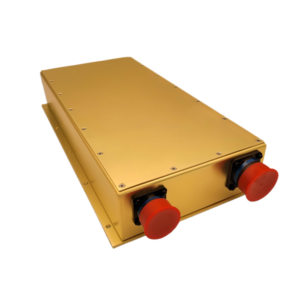
ETA-USA’s CH-M500CH-M1000 , and CH-M2000 series meets 115Vac 60Hz power profiles and used mil-approved D38999 connectors as standard.


MIL-STD-1399 Section 300B (DC Power) – Key Highlights

Section 300B covers DC-powered systems, typically using:

  • 24 VDC

  • 28 VDC

It specifies:

  • Voltage regulation tolerances

  • Ripple voltage limits

  • Load step response

  • Noise immunity and conducted emissions

This section is especially relevant for:

  • Fire control systems

  • Lighting and emergency gear

  • Communication equipment


 Who Needs to Comply?

MIL-STD-1399 applies to:

  • OEMs building systems for naval platforms

  • System integrators developing shipboard electronics

  • Defense contractors working with the U.S. Navy or allies

Any electronic system that plugs into ship power must be tested for compatibility, stability, and survivability under MIL-STD-1399 specifications.


 How Compliance Is Verified

While MIL-STD-1399 itself doesn’t prescribe test procedures, compliance is typically verified through:

  • Interface Control Documents (ICDs)

  • Power conditioning analysis

  • Bench testing using MIL-STD power simulators

  • Lab or on-board trials under nominal and off-nominal conditions

EMC compliance testing is often done in parallel using MIL-STD-461.


 Design Considerations for MIL-STD-1399

If you’re developing shipboard equipment, here’s what you should do early:

  •  Design for wide AC voltage and frequency tolerance

  •  Include EMI filters to reduce conducted emissions

  •  Provide hold-up time for power sags

  •  Confirm grounding schemes meet ship standards

  •  Test with power simulation equipment mimicking naval power profiles

 Pro tip: MIL-STD-1399 is not just a design goal—it’s a system integration requirement. Even if your product is COTS (commercial off the shelf), it must be qualified for shipboard use.


MIL-STD-1399 ensures that shipboard systems don’t just function—they integrate. It prevents power issues, communication errors, and costly retrofits by defining clear electrical expectations upfront.

For naval electronics, it’s not enough to be rugged and high-tech. You also need to be electrically compatible with the rest of the ship. MIL-STD-1399 bridges that gap between smart technology and real-world integration. Here are some of ETA-USA’s products designed to meet MIL-STD-1399 :

CH-M500 Series

CH-M1000 Series

CH-M2000 Series

Are these what you’re looking for? ETA-USA can also design power supplies to meet your requirements. Please do not hesitate to contact us.

MIL-STD-810: The Gold Standard for Rugged Equipment Testing

MIL-STD-810: The Gold Standard for Rugged Equipment Testing 

When designing equipment destined for military or harsh environments, one question always comes up: “How do I ensure my product will survive tough conditions?”

Enter MIL-STD-810 — the U.S. military’s cornerstone standard for environmental testing of equipment. If you want your product to be rugged, reliable, and ready for real-world use — this standard is your go-to guide.

In this post, we’ll explore what MIL-STD-810 is, why it matters, and how you can leverage it to build tougher products.


What is MIL-STD-810?

MIL-STD-810 ( Military Standard 810) is a test method standard developed by the U.S. Department of Defense. It outlines how to simulate environmental stresses that equipment might face in actual use — like temperature extremes, shock, vibration, dust, humidity, and more.

Instead of just guessing how a device will perform, MIL-STD-810 gives you a scientific, repeatable way to test durability.


Why MIL-STD-810 Matters

  • Real-World Relevance: The standard focuses on conditions soldiers and equipment actually face — desert heat, arctic cold, tropical humidity, rough transportation, and battlefield shock.

  • Product Confidence: Passing MIL-STD-810 tests means your device is tough enough for harsh conditions, which reassures users and buyers.

  • Market Access: Many government and defense contracts require MIL-STD-810 compliance or testing.

  • Rugged Brand Image: It’s a great marketing point for “ruggedized” consumer and industrial products too.


Key Test Categories in MIL-STD-810

MIL-STD-810 includes over 20 test methods, but some of the most common are:

1. Temperature Testing (High and Low)

  • Tests operation and storage in extreme cold and heat

  • Includes rapid temperature changes (thermal shock)

2. Humidity

  • Exposure to prolonged high humidity to check for corrosion and electrical failures

3. Vibration

  • Simulates vibrations from vehicles, aircraft, or rough handling during transport

  • Random and sinusoidal vibration profiles

4. Shock and Drop

  • Tests impact resistance to drops, bangs, and sudden shocks

5. Dust and Sand

  • Ensures protection against dust ingress during desert deployment or dusty environments

6. Rain and Water Spray

  • Tests resistance to rain, splashes, and water jets

7. Altitude

  • Simulates high-altitude conditions, including low pressure and cold


How Does MIL-STD-810 Testing Work?

1. Tailoring

  • MIL-STD-810 is not “one size fits all.”

  • You tailor the test plan based on the equipment’s expected environment — for example, if your device is for naval use, you might focus more on salt fog and humidity tests.

2. Test Setup

  • Testing is performed using specialized chambers and equipment replicating the conditions (e.g., environmental chambers, vibration tables, shock machines).

3. Pass/Fail Criteria

  • Your device must maintain functionality and avoid physical damage during and after testing.


Common Myths About MIL-STD-810

Myth 1: It’s a checklist of tests you must pass.
Truth: MIL-STD-810 is a guide. You select and tailor the tests based on your product’s mission profile.

Myth 2: Passing MIL-STD-810 means your product is indestructible.
Truth: It means your product meets specific environmental criteria — not that it can survive every possible scenario.


Practical Tips for Using MIL-STD-810

  • Understand Your Environment: Talk to users and study the deployment scenario before picking tests.

  • Start Early: Incorporate ruggedness into design before testing. Testing late can be costly.

  • Document Everything: Test setups, procedures, and results should be well documented for certification and troubleshooting.

  • Work with Experienced Labs: Accredited test labs can guide you through test tailoring and execution.


The MIL-STD-810H standard outlines environmental test methods for military equipment—including power supplies—to ensure their reliability and durability under harsh operating conditions. While MIL-STD-810 doesn’t contain “pass/fail” criteria by itself, it provides test procedures that manufacturers must perform to simulate real-world environments.

Below is a breakdown of MIL-STD-810H methods that commonly apply to power supplies, along with what they test and typical criteria:


Relevant MIL-STD-810H Methods for Power Supplies

Method Test Name Purpose for Power Supplies
500.6 Low Pressure (Altitude) Ensures performance at high altitudes; tests for arcing and insulation breakdown.
501.7 High Temperature Tests operation and storage at elevated temperatures.
502.7 Low Temperature Verifies function in cold environments (down to -51 °C for storage).
503.7 Temperature Shock Ensures survival during sudden changes in temperature (e.g., −40 °C to +70 °C in <1 min).
505.7 Solar Radiation (Sunshine) For exposed systems—tests UV aging, heating, and material degradation.
506.7 Rain / Blowing Rain For waterproof enclosures—tests ingress protection. Often paired with IP ratings.
507.7 Humidity Tests for condensation, corrosion, and insulation failure in humid environments.
508.8 Fungus For organic insulation or coatings—ensures materials don’t degrade when exposed to biological growth.
509.7 Salt Fog Simulates marine environments—important for corrosion resistance of PCB and connectors.
510.7 Sand and Dust Ensures enclosures are sealed against particulate intrusion.
514.8 Vibration Simulates vibration from transport, launch, or shipboard operations (e.g., helicopters or submarines).
516.8 Shock Drop and mechanical shock resistance—tests unit survivability.
521.4 Icing/Freezing Rain Tests surface and mechanical function after ice accumulation.
528.1 Mechanical Vibrations of Shipboard Equipment (Type I) Simulates shipboard vibration patterns—particularly relevant to submarines and naval systems.

Criteria and How They Apply to Power Supplies

MIL-STD-810 does not prescribe fixed pass/fail limits. Instead:

  • You define the operational and non-operational limits based on:

    • Your power supply’s intended deployment (e.g., aircraft, submarine, desert).

    • Customer specs (military, defense contractors).

    • Mission profile data.

Example: For Method 501.7 (High Temp)

  • Operating temp range may be defined as: 0 °C to 70 °C

  • Storage temp range may be −40 °C to 85 °C

  • You must demonstrate the PSU functions normally during and after exposure within those parameters.


Example: A Power Supply for Naval/Submarine Use

Let’s say you’re qualifying a rugged DC-DC power supply for a submarine:

Test Application Typical Limits
509.7 (Salt Fog) Prevents corrosion of terminals & PCBs 5% salt solution for 48 hours
507.7 (Humidity) Tropical/humid deployments 95% RH, 30–60 °C for 10 days
516.8 (Shock) Resists dropping or explosion shock 40g for 11 ms
514.8 (Vibration) Shipboard vibration (per MIL-STD-167) Profile depends on mounting type

Summary: Design Considerations for Compliance

To pass MIL-STD-810H tests, your power supply must include:

  • Robust mechanical design: shock-absorbing mounts, ruggedized enclosures

  • Thermal management: heatsinks, thermal pads, proper derating

  • Conformal coating or potting: for humidity, fungus, and salt fog resistance

  • Connector and housing sealing: dustproof, waterproof designs (often IP65+)

  • Low EMI emissions and high immunity: Often paired with MIL-STD-461G

Common Environmental Parameters for MIL-STD-810 Power Supplies

Category Typical Design Parameters Relevant Test Methods
Operating Temperature –40 °C to +70 °C (sometimes –55 °C to +85 °C) 501.7 (High Temp), 502.7 (Low Temp)
Storage Temperature –55 °C to +85 °C 501.7, 502.7
Altitude / Pressure Up to 15,000–40,000 ft (depending on use) 500.6 (Low Pressure)
Humidity 95% RH, cycling 30–60 °C for 10–14 days 507.7
Salt Fog 5% NaCl solution, 48–96 hours 509.7
Fungus Resistance 28-day exposure, ASTM G21 compliant 508.8
Thermal Shock –40 °C to +70 °C, 5–10 cycles 503.7
Solar Radiation (if exposed) 24h/day cycles for 10 days, UV spectrum 505.7

Mechanical Stress Parameters

Stress Type Common Test Limits Method
Vibration (Random / Shipboard) 1.0–7.7 Grms, 5–500 Hz, 1 hr/axis (X, Y, Z) 514.8 (Category 4, 20, 24)
Mechanical Shock 20–40 g, 11–18 ms, half-sine, 3 axes 516.8
Drop Shock 1-meter drop, unpowered 516.8 (Proc IV)
Shipboard Vibration 5–33 Hz sinusoidal, 1 hr/axis 528.1
Ingress Protection IP65 to IP67 (for outdoor/submarine enclosures) Supplementary

Materials and Construction Expectations

Parameter Typical Requirement
Coating (PCB) Conformal coating (MIL-I-46058C or IPC-CC-830)
Sealing Waterproof gaskets, epoxy, or potted enclosures
Corrosion Resistance Anodized, stainless, or marine-grade coatings
Connectors MIL-grade circular or shielded connectors
Shock Mounting Rubberized isolation for PCB or chassis

Electrical Performance Under Environmental Stress

Test Typical Requirement
Voltage Regulation ±1–5% across temp and load
Output Ripple <100 mV (varies with application)
Efficiency 80% or higher (often 85–90%)
Hold-Up Time 10–20 ms minimum
EMC Compliance MIL-STD-461G (often required jointly)
Thermal Protection Internal shutdown above 85–95 °C
Overvoltage / Short Circuit Self-recovery or fail-safe modes

ETA-USA Mil-Std compliant power supplies are designed to meet the non-operational storage temperature and vibration/shock specifications for transportation. All units are conformally coated to mitigate salt fog exposure and humidity requirements during operation.  For specific environmental conditions, contact an ETA-USA representative, our technical team respond in less than 24 hours for all technical questions. 

US Government and Defense industry customers are recommended to view our capability statement

MILITARY GRADE PRODUCT – 2,000W Conduction Cooled AC/DC Power Supply

CH-M2000 Series- Military Grade Conduction Cooled AC/DC Power Supply

ETA-USA line of conduction cooled military grade AC/DC power supplies provide the single solution to power your military & defense application. Customers may use the standard input & output connector or request their own. Meets Mil-std 461G ground, airborne, and ship-board systems including Mil-std 1399 sec 300 for 50/60 Hz systems. Units can be built in as little as 5 weeks.

CH-M2000 series Datasheet

Features

  • Input: 95~264 VAC in, 50/60/400 Hz (47~440Hz) operation
  • Available voltages: 12, 24, 28, 48
  • In-rush current limited
  • 8″ x 14″ footprint (excluding connectors)
  • Aluminum Enclosure with chromate finish for corrosion resistance and low resistance bonding
  • Conformal coated internal circuitry
  • Mounting: Two rows of five, 0.20″ diameter thru holes for secure mounting and thermal conductivity
  • >20 msec Hold Up time at full load, 115VAC input, >50 msec at 220 VACin.
  • DC  Output Regulation: Less than 10 mV voltage drift from 0 to full load (measured at output terminal)
  • Ripple and Noise: <1% peak-to peak
  • Constant Current OCP Protection
  • Operating Altitude: 15,000ft & 40,000ft at 8 kPa (55,000 ft max)
  • Weight: 9.5 lbs (Standard Unit)

Mil-Standard Compliances (Without External Circuitry)

  • EMI: Mil-Std 461, CE101, CE102, RE102
  • Susceptibility: CS114, CS115
  • Input Transient Mil-Std 704
  • Surge protection: Mil-Std 1275
  • Power Factor: Mil-Std 1399 sec 300A
  • Meets Mil Std-1399 Sec 300A Power Profile for 115V 60Hz systems & CVN class 78
  • Environmental/Shock/Vibration: Mil-Std 810

Available Modifications

  • Hard Anodized Enclosure with EMI Grounding
  • Mil-Std 901 Shock Compliant Enclosure (Product Dimensions Subject to Change)
  • IP66 or IP67 Enclosure
  • Customized Input and Output Connector
  • External Voltage Trim (10%, 20%)
  • Remote On/Off
  • I2C Status Reporting (Output Voltage, Output Current, Internal Temperature)
  • Three Phase Wye or Delta Input (Contact ETA-USA Representative for Details)
  • Increased Power output (2150W @ 24V & 28V, 2200W @ 48V)

See our 500W AC-DC MIL-STD Power Supplies

CH-M500 Series Datasheet

See our 1000W AC-DC MIL-STD Power Supplies

CH-M1000 Series Datasheet

See our Compact 1100W AC-DC MIL-STD Power Supplies

CH-M1100 Series Datasheet 

Contact ETA-USA for Product Availability and CAD Files. 

See Our Full Line of Military and Aviation Power Supplies 

Government Customers- See Our Capability Statement